Wednesday, 12 August 2015

JT65-HF HB9EQX Edition

As part of my exploration into the, new to me, JT65 mode I have found lots of pieces of software written to make the use of the mode. One of which is JT65-HF HB9HQX Edition which is currently at version 0.9.98.0
Obviously a lot of work has gone into this and joy of joys it interfaces really well with Ham Radio Deluxe. When first launched it asks you for your station details, the rig connection, the sound cards and whether you are using CAT. It also asks you what form of logging you have. A lot of the extensive settings can be left at the default,
The main screen
If you are using Ham Radio Deluxe with CAT simply choose the "Cat is enabled via Ham Radio Deluxe.." option and, assuming you already have HRD working fine, it will work seamlessly. You do have to stop DM780 before you start JT65-HF however.

Choose HRD on the CAT tab

The screen shows the waterfall in the narrow portion and the dialog exchange in the main scrollable window. If you have CAT working successfully the frequency and band are in the QRG and Band boxes top left. Above the current date and time are the audio input level and a user defined output level.


Conversation buttons


The main buttons controlling the dialog exchange are on the right hand side and are arranged in a logical order. They conveniently change colour throughout a QSO which is useful if you are wondering what to press next!


When you have finished the QSO button you simply press the Log QSO button and a dialog box allowing you to customize any message appears. Clicking the next Log QSO button actually writes the entry to the logbook - in my case the HRD logbook.

Log QSO
What I have found though is if you have HRD to automatically send an eQSL to eQSL.cc it doesn't work when using this method of log addition. You have to manually select the QSO's in HRD Logbook and upload them to eQSL manually. Not a great problem but if you were waiting for that elusive QSL card and wondering why this is the reason. Also if you normally use QRZ.COM to enter the various station fields from within HRD Logbook you will find that the stations added from JT65HF will need refreshing to get their full details. Again not a problem you just need to be aware of it.

Simple QSO operation.

If everything has been setup correctly, the application communicating with the rig, the soundcard levels set, the rig tuned to one of the JT65 frequencies (you can select them from the QRG pulldown) and the antenna tuned you can just sit and watch contacts appearing on the Exchange screen.


CQs and DX calls appear in green, existing exchanges between stations are shown in blue. Your signals are shown with a white background. This is all assuming you use the default colours.

The exchange box

The waterfall shows a graphical representation of what is being recieved. You can also set it so it shows the callsigns of the stations. You current transmit frequency is highlighted by a red bar above the waterfall.

A typical waterfall display


To reply to a CQ request you simply left click (on a Windows PC) on the green highlighted entry. This automatically populates the "Generated Text" field with a suitable reply. This by convention is their callsign, your callsign and your locator square. Then at the start of the next minute the application transmits this message.

The reply to you showing the initial signal report -02 dB

Replies to you are in pink and you can see the 73 message
The station will then reply back with a signal report - the displayed colour is pink. In the meantime JT-65HF highlights the next appropriate button to press. In this case it is the R-db button. It then populates the Generated Text field with his station, your station and a R with a reading of the dB sent field.


The next button to press is automatically highlighted
The other station then replies back with either RRR or 73. You click on the 73 button and again the relevant text is populated in the reply box and the QSO is finished.
Finally you click on the Log QSO button and it will make an entry in your log.


If you have enabled sound it will also sound a CQ in morse on your shack monitor when somebody has sent a CQ. You can also set the sound to warn you if somebody has replied back to you. I have mine set to G8YPH in morse. There are other sounds you can set too.

If you have already worked a station on JT65 before then their entry in the exchange screen is marked in a dark green colour and it says QSO B4 at the tail end of the entry which is convenient.
QSO B4

There are many more features of this well written program and I have found so far that it is by far the easiest to use. The only limitation is that is only 1 mode available and that is JT65 so if you want to use it on 6m with JT6M you can't.

Tuesday, 11 August 2015

HRD 6.3.0.410 installation

August 10th 2015 and Ham Radio Deluxe 6.3 was released. I downloaded it and tried the installation on a domain connected machine and the routine came up with the usual issues with registry keys as I reported on earlier posts for older versions of the software.

I logged out of the domain and then just logged in locally to the PC. I ran the installation routine again and everything worked perfectly. At the end of the installation I didn't run HRD instead just closing it down and logging off.

When I logged on as a domain user again and launched HRD all my old settings were still present, the logbook was intact and all the customization's to the screens were still there. I'm very happy.

Now all I have to do is operate the software in anger and see what issues if any there are. Straightaway I can see the previous problem with scrolling waterfall hiccups has been cured. It is now very smooth and judder free.

Monday, 10 August 2015

WSJT-X JT65 Operation using the Yaesu FT-450D

I decided to have a look at the JT digimodes to see if I decipher these strange tones I'd heard. For those people unfamiliar with JT these modes have been designed to allow amateurs to have QSO's using 13 character overs using very low power and hence very weak signals. A typical over would be:

  • Call CQ with the Maidenhead locator
  • Establish contact
  • Exchange signal reports
  • Wish each other best wishes and terminate the QSO
There are several packages available on the internet for transmitting/receiving/decoding these very weak signal protocols. One of which is  WSJT-X available from here that I for one have found very easy to setup and use.

WSJT-X wide waterfall

After installation of the software you go to the setup screen and enter your Callsign and locator square. Then you set the sound cards that you are using, choose the rig from an extensive database on a pulldown and then set the COM port settings and whether to let the rig CAT control the PTT.
All very simple to do and so much easier than the other popular program WSJT.

WSJT-X setup screen with specifics
for my FT-450D and the COM port configuration


However WSJT-X does have a limitation in that it currently (August 2015) encodes/decodes JT65 and JT9 protocols. Whereas WSJX contains all sorts of exotic modes - but I never managed to get the latter to key the transmitter so it is irrelevant to me!

I switched the rig on, loaded the WSJT-X program, set it to JT65 mode, got it to tune the rig to 14.076 MHz (the CAT control works well as long as you first set the Yaesu FT450D to VFO mode and USB/DATA) and just listened for a while to see what it would pickup.

WSJT-X showing typical activity on the entire portion of the band
(the equivalent of Supersweeper in DM780) in the left hand side of the pane
and a QSO received on the current receive frequency on the right hand side.
The receive/transmit audio frequencies can be seen on
their respective pulldowns
The receive (green) and transmit (red)
audio frequencies can also be seen in the waterfall

It seems that JT modes can be set to transmit on even or odd minutes and transmit 13 characters at a time.
Checkbox to set transmitting in even minutes

Musical notes

JT65 and similar modes sound like a piccolo flute to the human ear. WSJT-X has a waterfall display that shows the various signals in a graphical form that it is picking up. At the end of a transmission the decoder kicks in an a series of QSO's appear on the left hand side of the main display.

After a segment of listening a typical QSO looks similar to this:

  • CQ G8YPH IO83    - A CQ call is made by G8YPH with the locator square
  • G8YPH K1ABC FN42 - K1ABC responds back with their locator square
  • K1ABC G8YPH -21  - G8YPH sends a signal report
  • G8YPH K1ABC R-19 - K1ABC acknowledges and sends a signal report
  • K1ABC G8YPH RRR - G8YPH sends an acknowledgement
  • G8YPH K1ABC 73 - K1ABC sends best wishes and the QSO is complete


As this one station is set to transmit on odd minutes and the other is on even minutes the minimum amount of time for the QSO is 6 minutes. Of course you might both be on even minutes (I've seen some stations doing that for some odd reason) so it could take 11 minutes to do the QSO! You just have to be patient whilst operating this mode.

Power settings

The power settings of the rig are normally quite low - initial contact could be 20 watts dropping to 5 watts. Worldwide communication is possible using these modes with quite modest power settings and antenna setups. I'm going to investigate the modes more as my first contact was on 20m with a station in Moldova. This was a country I hadn't worked on any mode despite it being in Europe. I left the rig on just listening and Chinese stations were clearly seen and worked - another country I had never been able to work on fatter bandwidth modes. China is some 8000 miles away from this station QTH and both this station and the Chinese station were running just 5 watts.

Unfortunately this particular piece of software will not work with Ham Radio Deluxe yet so I have to unload the HRD rig control and DM780 software module. You can still have the HRD Logbook module running but have to enter any QSO's manually. I suppose it's only a matter of time until the JT modes are integrated.

Future operational details

I'll report on the various aspects of this software in future posts as I find out how best to operate it.
Watch this space....

73s de Terry G8YPH

Wednesday, 5 August 2015

2 rigs 2 antennas 2 coaxial switches - Part 2

The Diamond CX-210A switches arrived along with some high spec 0.5m long patches leads terminated either end with PL259 plugs.

I cut a small piece of plywood on the table saw and mounted both switches side by side with the supplied screws. One of the patch leads was connected between the switches as per my circuit diagram outlined in Part 1.


The other two patch leads were used to connect to the two rigs. The antennas were then connected to the switches output as per the photo.

I placed the switch assembly board behind both rigs on the desk. In operation I just exercise a few muscles and get out of the shack chair to throw each switch! No need for it to be in finger tip reach.

The insertion loss for each switch is 0.05dB from DC to 500MHz and I have not noticed any issues with loss of sensitivity of either rig. I just worked a couple of stations in Argentina and Brazil (about 8000 miles away) on 35 watts PSK31 so neither transmission nor reception have been impacted. VHF/UHF on the FM transceiver is ok too with a distant repeater in Birmingham (about 72 miles away) still being workable on 2m.

Tuesday, 4 August 2015

2 rigs 2 antennas 2 coaxial switches - Part 1

I have a couple of antennas and 2 base station rigs. The FM transceiver is quad band and is attached to a tri band antenna covering 6m/2m/70cm. The HF antenna is connected to a multi band antenna covering 40m to 6m including all the WARC bands. It is supposed to be able to resonate on 80m band too but I've never had any success with this.

With this in mind the 6m portion of the VHF/UHF antenna (Diamond V-2000) is an inverted Vee that is directional - despite "visually appearing" to be part of a vertically polarized antenna system. The VHF and UHF portions of the antenna are omnidirectional vertically polarized. I have the 6m portion pointing eastwards.

At times of 6m activity it would be nice to switch between the conventional HF antenna to the W-2000 on the HF rig to see if there are any differences. It is very inconvenient to reach around the back of each of the rigs to unscrew the antenna plugs and swap them over so I came up with this idea.
Using a pair of Diamond CX-210A 2 way coaxial switches I designed the circuit shown below.


There is no interlocking so there can become an issue where rigs are connected to nothing on occasion. However the good news is that the output of one cannot be connected to the output of another! As this is going to be used just by me I see no problem. I just have to remember to throw both switches at the same time. 

The antenna switches are connected the conventional way (the HF rig feeding the common connection) of the HF switch. The FM transceiver is connected to one of the switched connections of the VHF/UHF switch. In normal operation each rig is connected to its respective antenna. When I want to use the HF rig on the V-2000 I have to throw both switches to their other positions. I would also switch the FM transceiver off as it wouldn't be connected to an antenna at all.

There doesn't appear to be anything relatively cheap on the amateur market that can do this so in the spirit of ham radio I'm doing it myself. The switches and connectors have been ordered - watch this space!

Monday, 3 August 2015

Daytime HF band working - July/August 2015

I've found in the last few weeks (July 2015 to post date) that the HF bands have been very flat during the day. I used to hear the Worked All Britain (WAB) net on 40M (usually around 7.160MHz) most days prior to this from around 9AM to late afternoon when tuning around the bands. The net has been very infrequent of late.

I hear similar reports from other amateurs and 20m is fairly flat too. The one saving grace has been some fantastic activity on 6m occasionally, as is expected at these times of the year, with quite a lot of continental contacts on digimodes.

Of course the evenings and early mornings on 40m have been sensational of late. I don't get up that early but a few days ago, July 31st, was really good with USA to Europe and middle east (Israel in particular) coming through with 40db over 9 contacts. It's just a pity most of the dark hours are spent asleep by me!

73 de Terry

Thursday, 30 July 2015

Checking the input/output of a soundcard - use with an FT-450D

On the Facebook group for Ham Radio Deluxe somebody had posted a link to a video highlighting a "bug" in soundcards that use a particular Texas Instruments audio chipset - the affected chipset is the TI PCM2900 series PCM2904 and below, pre-C revisions. See here for Reddit article.

Some radios have this chipset built into them. My Yaesu FT450-D is NOT one of them fortunately.

I had a look at the YouTube video https://www.youtube.com/watch?v=guH0NMRRTAo and the poster John Sands had a lot of useful information including how to temporarily fix it if you have the chipset. There was a link to a freeware piece of software for a Peak Level Meter darwooddesigns.co.uk/pc2/meters.html and on the Facebook page of HRD somebody linked to a Soundcard Oscilloscope zeitnitz.eu/scope_en which can be used to check the waveform of your signals.

G8YPH Soundcard Usage

The PC connected to my various radios has 4 soundcards built into it:
  • The internal onboard Dell soundcard is disabled in the BIOS
  • A EMU-0404 PCI high spec professional soundcard - many input/outputs, ASIO, WAVE, Full MIDI, DSP configuration possible with this card - drivers up to Windows 7 64bit are only available for this now though. So Windows 8.1 and Windows 10 might not work.
  • 2 x USB cheap soundcards (costing a few quid from Amazon)

The latter soundcards are the ones that I use for the Yaesu FT-450D as they are connected to a powered USB hub close by the rigs.
The only issue I had to resolve with these sound cards are that they are not shielded. I added some domestic aluminium foil around the body and loosely connected it to the ground/earth of the USB plug. This simple modification worked very well and the dongle does not pickup any stray RF at all.
A long term modification would be to replace the aluminium with self adhesive copper foil wrapped around the case with a soldered connection to the ground. However for the time being the aluminium works well.
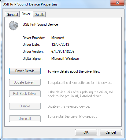
The sound card automatically picks up the necessary drivers from Microsoft's Windows Update site and the driver it uses is:

  • USB PnP Sound Device
  • Driver Provider: Microsoft
  • Driver Date: 12/07/2013
  • Driver Version: 6.1.7601.18208
  • Digital Signer: Microsoft Windows
General Tab

Driver Tab

Driver Details


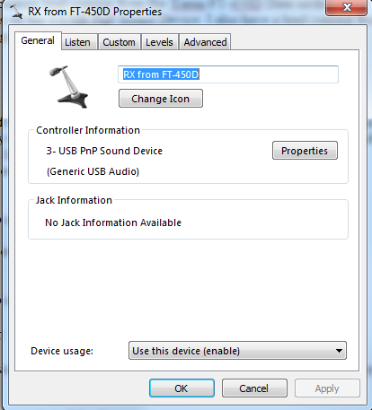
The controller information field shows up my cards as being 3-USB PnP Sound Device and 5-USB PnP Sound Device (Generic USB Audio)

If you plug the device into a different USB socket it will pickup a different number.


Naming sound cards

Recording Device Naming

Playback Device Naming

It's always a good idea to name any devices you have in Windows from the defaults ones. It aids signal tracing later on.
I have named my devices as this:
3-USB PnP Sound Device - from now on known in the blog as Soundcard #3
  • Recording - RX from FT-450D
  • Playback - TX to FT-450D


5-USB PnP Sound Device - from now on know in the blog as Soundcard #5

  • Recording - FT-450D Headphone Socket
  • Playback - NOT IN USE - I don't use this currently for anything.


The 3.5mm (1/8") plugs on the custom lead coming from the Yaesu FT-450D Data socket are plugged into the relevant sockets on the 3-USB PnP Sound Device. I also have a lead coming from the headphone socket of the rig going to the recording socket of the 5-USB PnP Sound Device.

Sound Card Levels

As the input and output levels of the FT-450D data socket are fixed then you have to resort to using the digital attenuator supplied by the driver to the sound card. Fortunately the input and output of the rig are matched (impedance and line level) to the typical computer soundcard.
On Soundcard #3 I have the following for the "Recording" settings:

General Tab
This is where you change the name of the device and
change its icon

Listen Tab

NOTE AGC on the Custom Tab is disabled

Levels Tab

Advanced Tab

For the Soundcard #3 "Playback" settings I have this

General tab
I have renamed it to something meaningful

Levels tab
63% seems to work well for me
ALC is controlled from within DM780 itself
as seen in another of my blog posts

Enhancements tab
Nothing is selected here and left at default

Advanced tab
Again nothing is changed here


On Soundcard #5 I have the following settings for the "Recording" settings :
General tab
Note I have changed the Icon to a set of headphones

Listen tab
The "Listen to this device" checkbox is ticked
see further down for details

NOTE AGC on the Custom Tab is disabled

Level Tab

Advanced Tab

I don't use the playback section of the Soundcard #5 so haven't included it.

Monitoring the rig output

I have the recording input of device 5 set to playback through the default playback device - in my case the EMU-0404
To do this:
In the Sound manager open the properties of the device

  • go to the Listen tab
  • check the Listen to this device box
  • make sure the Default Playback Device is selected
  • Click OK twice.


You can then listen to the output of the the FT450D through the shack speakers and control the level using the AF Gain control on the rig (or control that with HRD Rig Control)

Monitoring sound card output

The Digital Level Meter software from darkwooddesigns.co.uk can be configured to monitor the input level of any of your sound cards.
I set mine to monitor Soundcard#3 microphone socket - this is connected to the rig data output socket. I tuned to a typical busy position of the 20m band which has a lot of activity - 14.070 MHz USB the PSK portion.
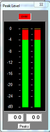
As the level of the digital attenuator is set to 49%  I get peaks of around -3.8dB and an average of -8dB which is just less that the software overload position.
A good peak level


I turned the attenuator up to 100% (so it wasn't doing anything) and immediately went into the red peaking at 0db - and flashing OVERLOAD - which I would have expected. This was also verified in the DM780 module too as everything was saying OVERLOAD

Bad peak level

As there was no way of turning down what is coming from the rig the only alternative is to activate the digital attenuator on the soundcard. This is not an ideal but the only thing I have.
I turned the attenuator back to 49% and all was well.

Using a digital oscilloscope to check the waveform for clipping.


The Soundcard Oscilloscope software can be used to check any permutation of soundcard within a PC. I had a look at the waveform of the signal on the Soundcard#3 microphone socket.


When set at 49% the signal was pure and smooth. When increased to 70% the peak level meter was just peaking into Overload also confirmed with DM780. The waveform on the Oscilloscope was also starting to clip.
I increased the level to 100% and the waveforms were continually clipping.

So I decreased the level back to 49% again and all returned to normality.

I think that level works well for me although I don't currently operate any of the JT65 or JT65-HF weak signal modes. These modes need your sound card set for optimum levels and the two pieces of software I highlighted can help in setting your station up to operate these modes.

Monitoring Sound Card Input,


It's always nice to see the signal that your PC is generating is at a good level and isn't introducing distortion into the start of the signal chain.
The Software Oscilloscope can be used to monitor the signal both coming from the computer and into the soundcard feeding the rig.

In my case I chose Loopback: TX to FT-450D
(aren;t you glad you named the soundcards earlier on!)

You can compare the waveform and make the necessary level adjustments.

A fairly smooth waveform being fed into the sound card


Conclusion

It is easy to monitor the levels and waveforms of digimode audio both going in and coming out of your rig using a few simple freeware programs. You can then make sure you are making the most of your computer by obtaining the cleanest possible audio signal.